
I had to repair a Gibson Les Paul boost circuit and drew out the diagram which does not seem to be available on the net so I thought I’d share. The 47k trimmer sets the boost gain. The 4.7pF caps are an educated guess. I think they are just there to avoid RF interference. It was odd but the source terminal of the J202 FET was connected to the 22k load resistor R3. I guess they are interchangeable.
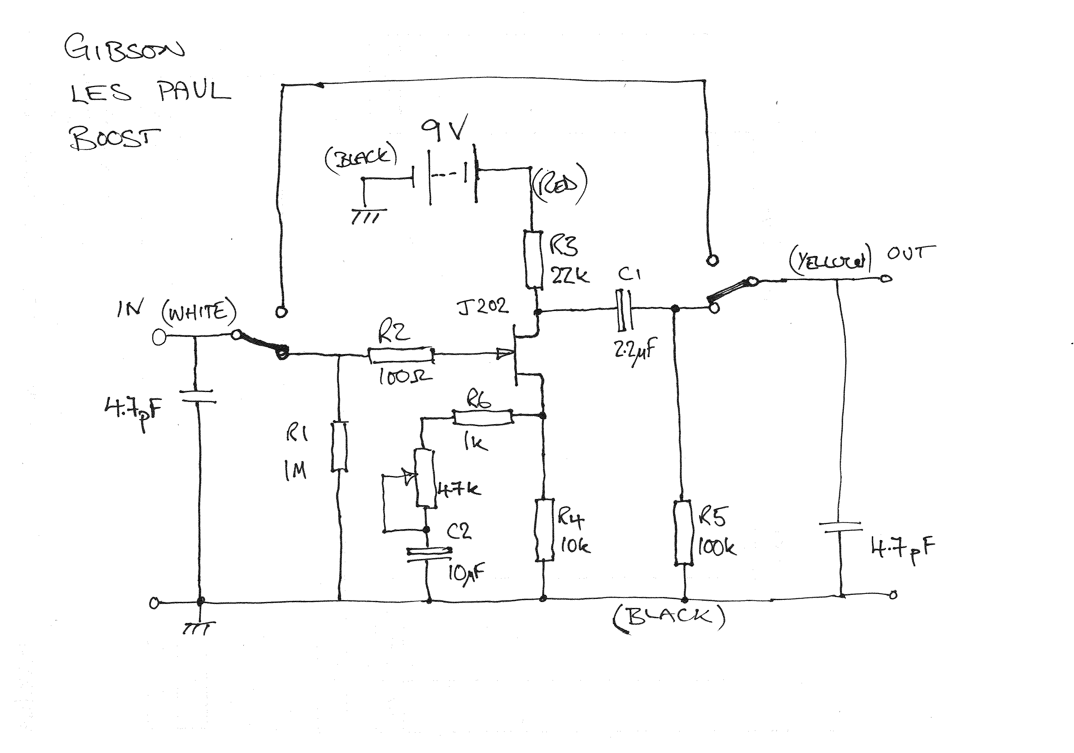
Gibson Les Paul Boost Circuit